This is the Series of tutorials on the STM32 Microcontroller. The aim of this series is to provide easy and practical examples that anyone can understand. In our last article, we have seen STM32 UART DMA Example. In this tutorial, we are going to connect Pendrive to STM32 – STM32 USB Host MSC Tutorial.
Table of Contents
Hardware Required
STM32 USB Host MSC – Connect Pendrive to STM32
STM32F767Zi has USB OTG Full Speed and USB OTG High-Speed capability (with the ULPI). The USB OTG is a dual-role device (DRD) controller that supports both device and host functions and is fully compliant with the On-The-Go Supplement to the USB 2.0 Specification. It can also be configured as a host-only or device-only controller, fully compliant with the USB 2.0 Specification.
In this article, we are going to see STM32 USB Host MSC (Host-Only mode).
We need to give the 48MHz clock to the USB OTG from RCC. The STM32 Nucleo-144 board supports USB OTG or device-full-speed communication via a USB Micro-AB connector (CN13) and USB power switch (U12) connected to VBUS.
STM32 USB Host MSC Example
Project Creation
Create the new STM32 project in STM32CubeIDE.
|
|
|
Note: This project was set up with STM32CubeMx V6.10 using STM32Cube FW_F7 V1.17.1.
Configure USART3 for Debug Prints
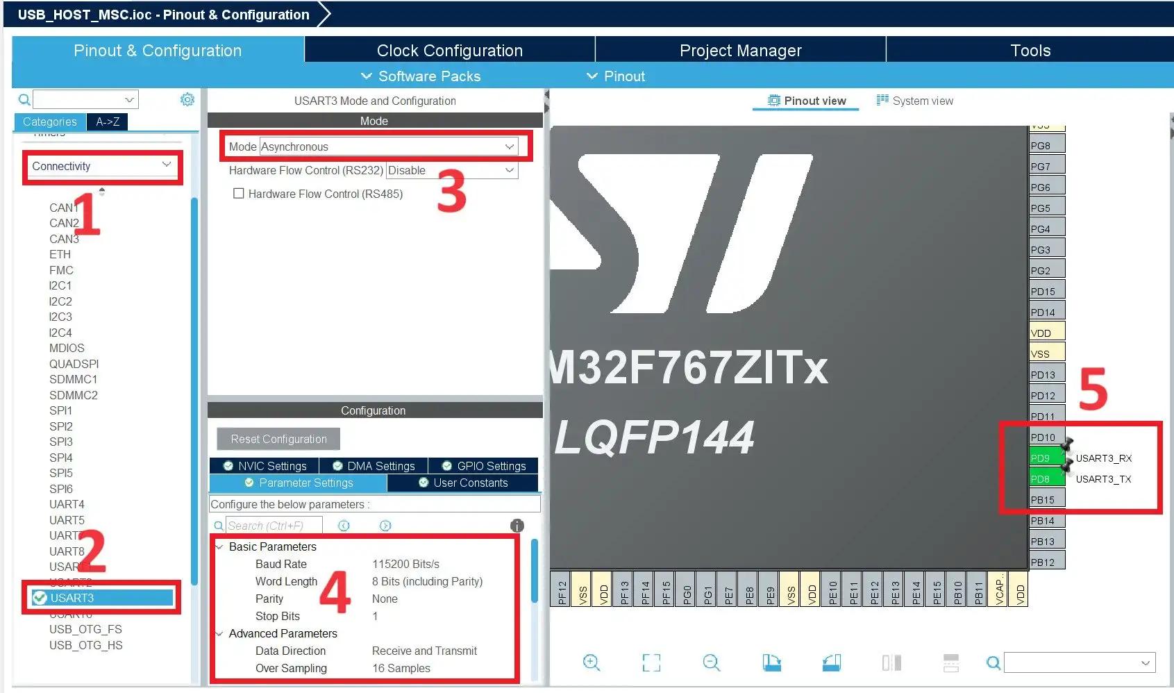
In the STM32F767Zi Nucleo board, USART3 is available as a virtual COM Port. So, we can use this USART3 for our debug prints. In the .ioc file, Click “Connectivity” –> “USART3“. Select Mode as Asynchronous. By default, PB10 and PB11 will be configured. But in our STM32F767Zi Nucleo board, PD8 and PD9 are used for Virtual Com Port. So, configure the PD9 and PD8 for USART3. Refer to the below image. The baud rate is 115200.
Configure USB OTG
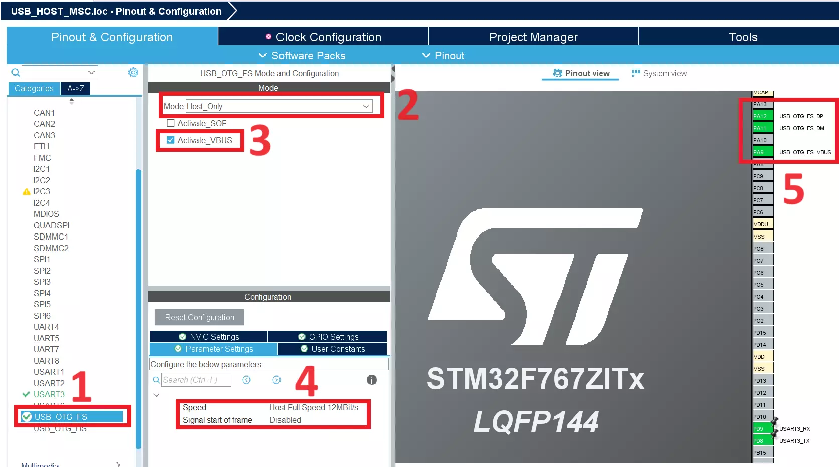
Click USB_OTG_FS, then set the Mode as Host_Only. After that, Activate the VBUS. Refer to the below image.
Configure USB HOST
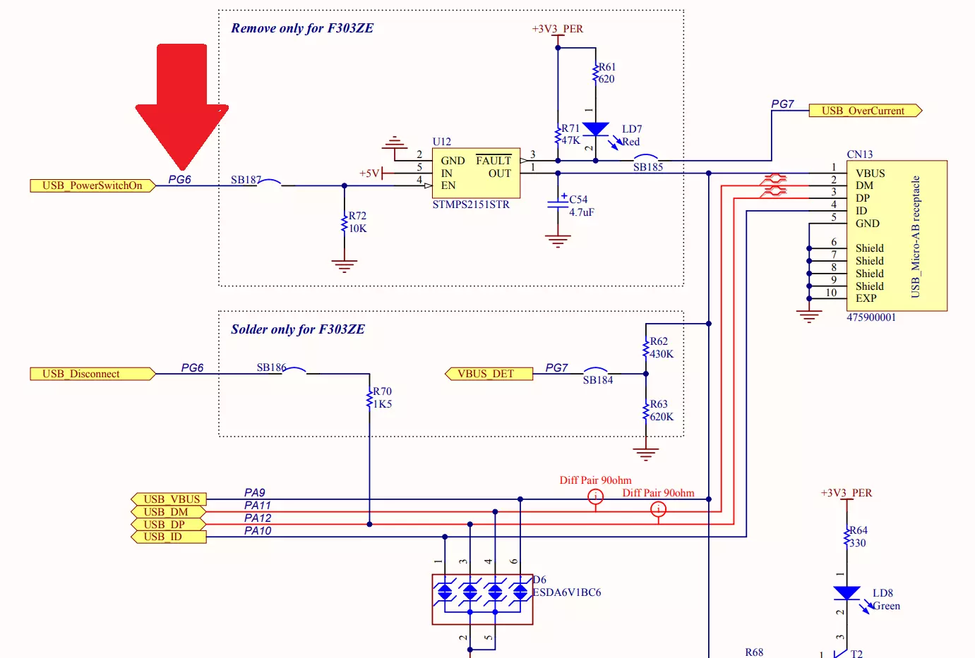
In the STM32F767Zi Nucleo board, PG6 GPIO is used to configure the VBUS. Refer to the below schematic diagram of the USB Connection.
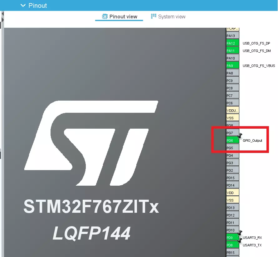
So configure the PG6 pin as Output like the below image. And set this GPIO to High by default.
|
|
|
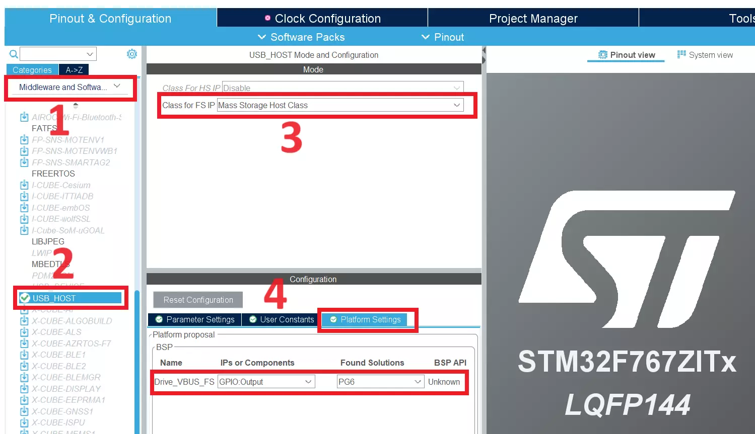
Now, click Middleware and Software –> USB_HOST. Then set the Class forFS IP to Mass Storage Host Class. Then in the Platform Settings, configure the PG6 to VBUS. Please refer to the below image.
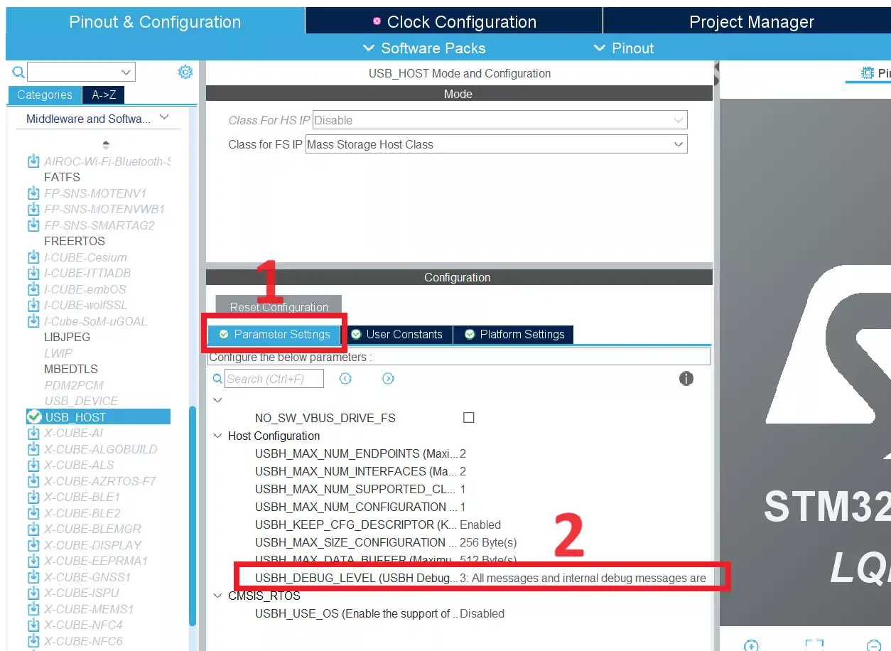
Now, we will enable the USB Log messages which will help us to debug the USB if any error. Click Parameter Settings and set the USBH_DEBUG_LEVEL to 3 like the below image.
Configure FatFs
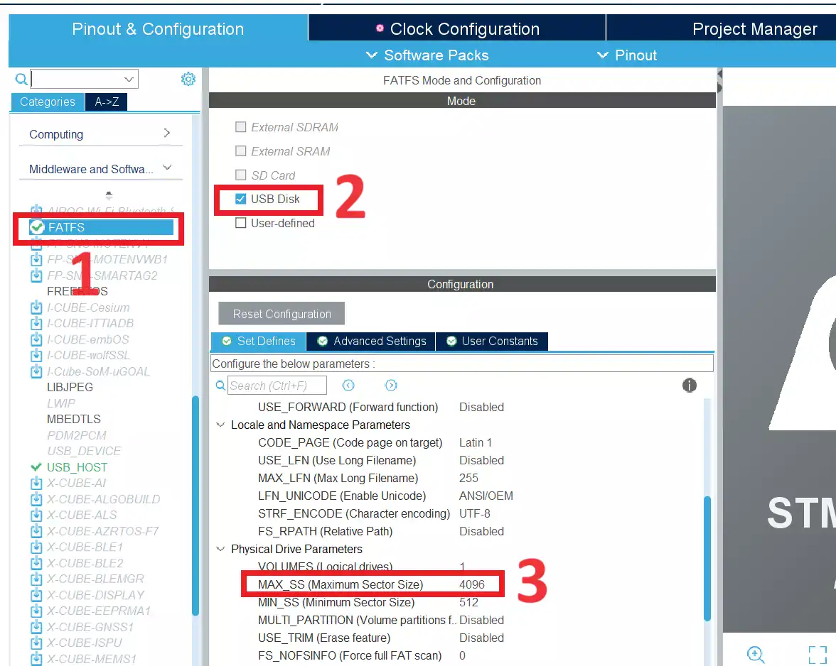
Now we will configure the FAT filesystem. Click FATFS and enable the USB Disk. Then set the MAX_SS to 4096 like the below image.
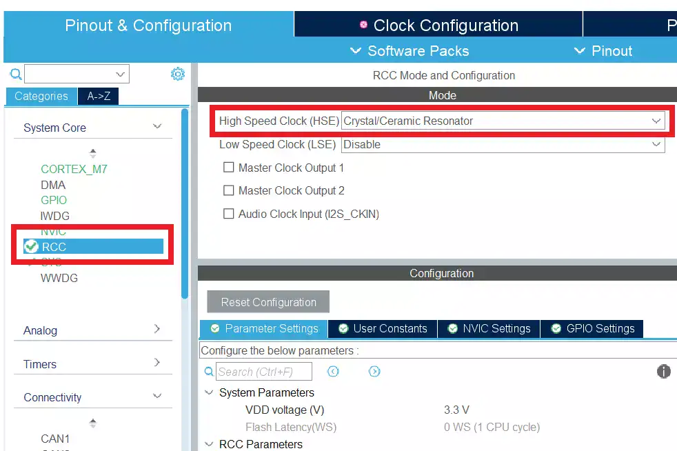
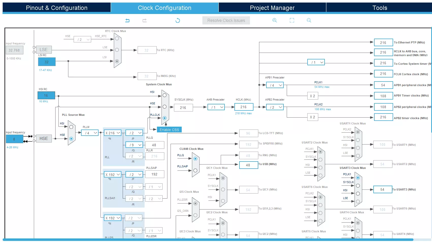
Configure Clock
We need to give the 48MHz to the USB. So configure the clock like the below image. We are going to use our HSE clock which gets 8MHz. Click RCC and Set the HSE to Crystal/Ceramic Resonator like the below image.
Then configure the clock like below.
|
|
|
Save the .ioc file and generate the code.
Source Code – STM32 USB Host MSC Example
[You can get the complete project source code on GitHub]
Note: If you are using the STM32F767Zi Nucleo board or STM32G0 board and STM23F7 Firmware Package V1.17.1, it has USB Host V3.4.1. This USB Host package has a bug. So, the USB won’t work as expected. To solve that issue, download the USB Host V3.5.0.
Delete the STM32_USB_Host_Library directory in the source code Extract this downloaded file instead of the deleted one. Check the below image.
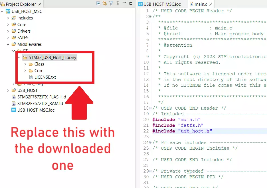
Note: Whenever you are re-generating the code, you need to replace that directory with the downloaded code once again.
|
|
|
Now add the below code to the USB_HOST--> App-->usb_host.c between USER CODE BEGIN 1 and USE CODE END 1.
/* USER CODE BEGIN 1 */
#include <stdio.h>
#include "fatfs.h"

extern UART_HandleTypeDef huart3;

/**
  * @brief Print the characters to UART (printf).
  * @retval int
  */
#ifdef __GNUC__
  /* With GCC, small printf (option LD Linker->Libraries->Small printf
     set to 'Yes') calls __io_putchar() */
int __io_putchar(int ch)
#else
int fputc(int ch, FILE *f)
#endif /* __GNUC__ */
{
  /* Place your implementation of fputc here */
  /* e.g. write a character to the UART3 and Loop until the end of transmission */
  HAL_UART_Transmit(&huart3, (uint8_t *)&ch, 1, HAL_MAX_DELAY);
  return ch;
}

static FRESULT ETX_MSC_ProcessUsbDevice(void)
{
  FATFS     UsbDiskFatFs;                                 /* File system object for USB disk logical drive */
  char      UsbDiskPath[4] = {0};                         /* USB Host logical drive path */
  FIL       file;                                         /* File object */
  FRESULT   res;                                          /* FatFs function common result code */
  uint32_t  total_space, free_space;                      /* Total Space and Free Space */
  DWORD     fre_clust;                                    /* Freee Cluster */
  uint32_t  byteswritten, bytesread;                      /* File write/read counts */
  uint8_t   wr_data[] = "Welcome to EmbeTronicX!!!";      /* Data buffer */
  uint8_t   rd_data[100];                                 /* Read buffer */
  char      file_name[] = "temp.txt";                     /* File name */

  do
  {
    /* Register the file system object to the FatFs module */
    res = f_mount( &UsbDiskFatFs, (TCHAR const*)UsbDiskPath, 0 );
    if( res != FR_OK )
    {
      /* FatFs Init Error */
      break;
    }

    /* Check the Free Space */
    FATFS *fatFs = &UsbDiskFatFs;
    f_getfree("", &fre_clust, &fatFs);
    total_space = (uint32_t)((UsbDiskFatFs.n_fatent - 2) * UsbDiskFatFs.csize * 0.5);
    free_space = (uint32_t)(fre_clust * UsbDiskFatFs.csize * 0.5);
    printf("USB Device Total Space = %lu MB\n", total_space/1024);
    printf("USB Device Free Space  = %lu MB\n", free_space/1024);

    /* Create a new text file with write access */
    res = f_open( &file, file_name, ( FA_CREATE_ALWAYS | FA_WRITE ) );
    if( res != FR_OK )
    {
      /* File Open Error */
      break;
    }

    /* Write the data to the text file */
    res = f_write( &file, wr_data, sizeof(wr_data), (void *)&byteswritten );

    /* Close the opened file */
    f_close( &file );

    if( res != FR_OK )
    {
      /* File write Error */
      break;
    }

    printf("Data written to the USD Device\n");

    /* Open the text file object with read access */
    res = f_open( &file, file_name, FA_READ );
    if( res != FR_OK )
    {
      /* File Open Error */
      break;
    }

    /* Read data from the file */
    res = f_read( &file, rd_data, sizeof(wr_data), (void *)&bytesread);

    /* Close the file */
    f_close(&file);

    if(res != FR_OK)
    {
      /* File Read Error */
      break;
    }

    /* Print the data */
    printf("Read Data : %s\n", rd_data);

  } while ( 0 );

  /* Unmount the device */
  f_mount(NULL, UsbDiskPath, 0);

  /* Unlink the USB disk driver */
  FATFS_UnLinkDriver(UsbDiskPath);

  return res;
}
/* USER CODE END 1 */
In the above code, __io_putchar or fputc is used for printf function. When we use printf, the prints will be sent to the USART3. So, we can use this for debugging purposes.
ETX_MSC_ProcessUsbDevice() function mounts the USB device and prints the storage details. Then it creates the file named temp.txt and writes the string (“Welcome to EmbeTronicX!!!”) to that file. Then read back the content of the file and print it. Finally, it unmounts the USB device and unlinks the USB disc path.
Add the below code to the function USBH_UserProcess()‘s case HOST_USER_CLASS_ACTIVE.
  if( ETX_MSC_ProcessUsbDevice() != FR_OK )
  {
    printf("USB Device Process Error\n");
    /* Error : Hang Here */
    while(1);
  }
So the complete USBH_UserProcess() function looks like below.
|
|
|
static void USBH_UserProcess  (USBH_HandleTypeDef *phost, uint8_t id)
{
  /* USER CODE BEGIN CALL_BACK_1 */
  switch(id)
  {
  case HOST_USER_SELECT_CONFIGURATION:
  break;

  case HOST_USER_DISCONNECTION:
  Appli_state = APPLICATION_DISCONNECT;
  break;

  case HOST_USER_CLASS_ACTIVE:
  Appli_state = APPLICATION_READY;
  if( ETX_MSC_ProcessUsbDevice() != FR_OK )
  {
    printf("USB Device Process Error\n");
    /* Error : Hang Here */
    while(1);
  }
  break;

  case HOST_USER_CONNECTION:
  Appli_state = APPLICATION_START;
  break;

  default:
  break;
  }
  /* USER CODE END CALL_BACK_1 */
}
USBH_UserProcess is a state machine that checks the different states, for eg- when the USB Connection, Disconnection, or When it is Ready for Communication. We will write our program once the Application is READY (APPLICATION_READY). That means the communication is established. So, We can do our file operations. That’s why we have called our function once the state is set to APPLICATION_READY.
Note: If you are using STM32F407 Discovery Board, then you need to check one more thing. The MX_DriverVbusFS() function from USB_HOST_Target->usbh_platform.c file should be like below. If state ==0, then we need to do GPIO_PIN_SET, otherwise GPIO_PIN_RESET.
/**
  * @brief  Drive VBUS.
  * @param  state : VBUS state
  *          This parameter can be one of the these values:
  *           - 1 : VBUS Active
  *           - 0 : VBUS Inactive
  */
void MX_DriverVbusFS(uint8_t state)
{
  uint8_t data = state;
  /* USER CODE BEGIN PREPARE_GPIO_DATA_VBUS_FS */
  if(state == 0)
  {
    /* Drive high Charge pump */
    data = GPIO_PIN_SET;
  }
  else
  {
    /* Drive low Charge pump */
    data = GPIO_PIN_RESET;
  }
  /* USER CODE END PREPARE_GPIO_DATA_VBUS_FS */
  HAL_GPIO_WritePin(GPIOC,GPIO_PIN_0,(GPIO_PinState)data);
}
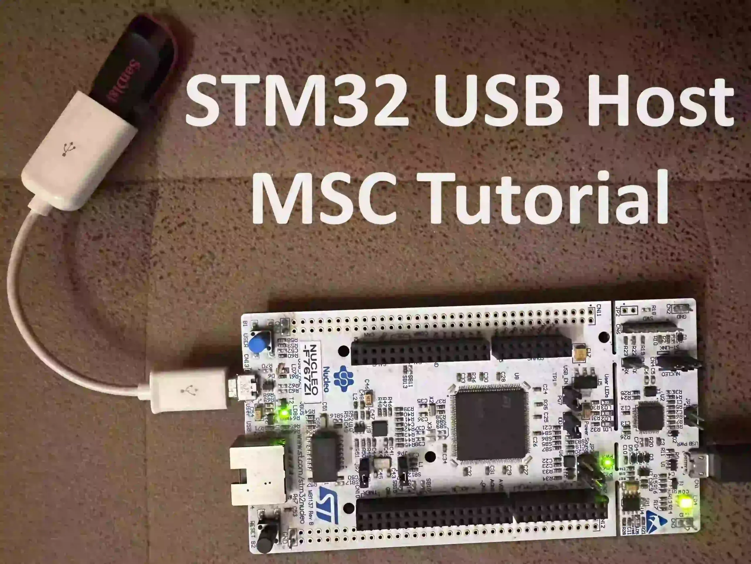
Hardware Connection – STM32 USB Host
We have connected the Micro USB OTG Adapter Host Cable and pen drive. Then connect the OTG Cable to the CN13 User USB. Check the below image. And make sure the JP4 (USB_EN) is ON.
Demo – STM32 USB Host FatFs Example
Connect the Pendrive to the PC and format it in the FAT32 filesystem.
The code is ready. Build the code and flash it. We have connected 16GB Sandisk Pendrive. You should get the prints like below.
|
|
|
USB Device Connected
USB Device Reset Completed
PID: 5567h
VID: 781h
Address (#1) assigned.
Manufacturer : SanDisk
Product : Cruzer Blade
Serial Number : 03024529092623093708
Enumeration done.
This device has only 1 configuration.
Default configuration set.
Switching to Interface (#0)
Class    : 8h
SubClass : 6h
Protocol : 50h
MSC class started.
Number of supported LUN: 1
LUN #0:
Inquiry Vendor  : SanDisk
Inquiry Product : Cruzer Blade
Inquiry Version : 1.00
MSC Device ready
MSC Device capacity : 3120561664 Bytes
Block number : 31260671
Block Size   : 512
USB Device Total Space = 15247 MB
USB Device Free Space  = 15247 MB
Data written to the USD Device
Read Data : Welcome to EmbeTronicX!!!
Connect the Pendrive to the PC and check. There should be a file called temp.txt and if you open it, it should contain a “Welcome to EmbeTronicX!!!” string.
Please read the other STM32 Tutorials.
In our next article, we will see STM32 USB Device MSC.
You can read the below tutorials.
|
|
|
Embedded Software | Firmware | Linux Devic Deriver | RTOS
Hi, I am a tech blogger and an Embedded Engineer. I am always eager to learn and explore tech-related concepts. And also, I wanted to share my knowledge with everyone in a more straightforward way with easy practical examples. I strongly believe that learning by doing is more powerful than just learning by reading. I love to do experiments. If you want to help or support me on my journey, consider sharing my articles, or Buy me a Coffee! Thank you for reading my blog! Happy learning!
