This article is the continuation of the Series on the ESP32 Tutorials using ESP-IDF and carries the discussion on the ESP32 and its peripherals. The aim of this series is to provide easy and practical examples that anyone can understand. In our previous post, we have seen how to setup the Visual Studio Code for ESP-IDF and executed the hello world program. In this post, we will see ESP32 GPIO tutorial using ESP-IDF.
Please read the GPIO article which explains how the GPIO works in all microcontroller and types of the GPIO.
Table of Contents
Hardware Required
- PC
- ESP32 Board
- LED
- Resistor (To limit the current through the LED)
- Connecting wires
- Bread Board
Introduction
The ESP32 is a versatile microcontroller that is widely used in the field of embedded system and IoT (Internet of Things). ESP32 has 48 pins which can do multiple functions. But not all the pins are exposed in the development board. Few pins cannot be used also. There are multiple ESP32 development boards are available in the marker including cloned boards.
In this series, we are going to use two ESP32 development boards which are 30 pin board and 38 pin board.
Before looking into the GPIO, we will see the pinout of the ESP32.
|
|
|
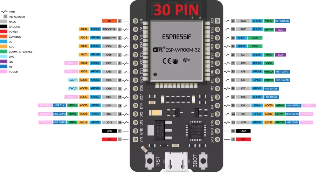
ESP32 30 Pin Development board Pinout
The below image illustrates the ESP-WROOM-32 chip pinout of 30 Pin ESP32 Development board.
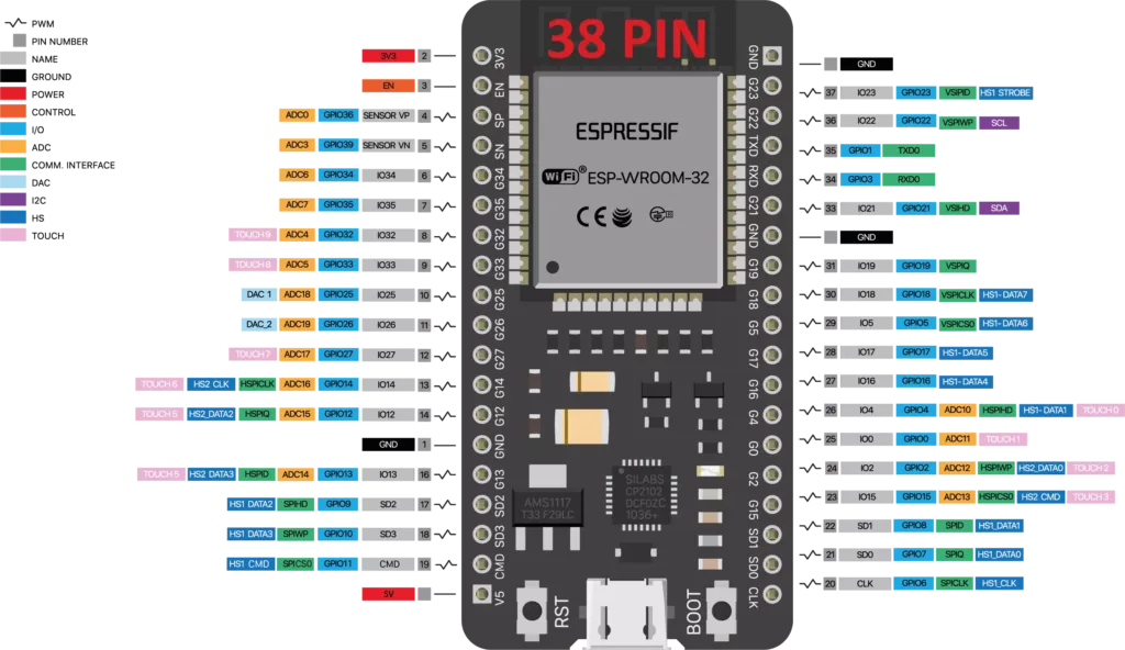
ESP32 38 Pin Development board Pinout
The below image illustrates the ESP-WROOM-32 chip pinout of 38 Pin ESP32 Development board.
ESP32 Pins
ESP32 pins are used for multiple functions. Those pin supports the below functionalities.
- 18 Analog-to-Digital Converter (ADC) channels
- 3 SPI interfaces
- 3 UART interfaces
- 2 I2C interfaces
- 16 PWM output channels
- 2 Digital-to-Analog Converters (DAC)
- 2 I2S interfaces
- 10 Capacitive sensing GPIO’s
In this tutorial, we are going to see on the GPIO functionality. We will see other functionalities later part of this ESP32 tutorial series. The ESP32 chip features 34 physical GPIO pins (GPIO0 ~ GPIO19, GPIO21 ~ GPIO23, GPIO25 ~ GPIO27, and GPIO32 ~ GPIO39). Each pin can be used as a general-purpose I/O, or be connected to an internal peripheral signal.
GPIO34 to GPIO39 are only input pins and it won’t support output. These pins don’t have internal pull-ups or pull-down resistors. So we can use these pins only as inputs.
|
|
|
The table below provides more information on pin usage, and please note the comments in the table for GPIOs with restrictions.
| GPIO | Analog Function | RTC GPIO | Comments |
|---|---|---|---|
| GPIO0 | ADC2_CH1 | RTC_GPIO11 | Strapping pin |
| GPIO1 | TXD | ||
| GPIO2 | ADC2_CH2 | RTC_GPIO12 | Strapping pin |
| GPIO3 | RXD | ||
| GPIO4 | ADC2_CH0 | RTC_GPIO10 | |
| GPIO5 | Strapping pin | ||
| GPIO6 | SPI0/1 | ||
| GPIO7 | SPI0/1 | ||
| GPIO8 | SPI0/1 | ||
| GPIO9 | SPI0/1 | ||
| GPIO10 | SPI0/1 | ||
| GPIO11 | SPI0/1 | ||
| GPIO12 | ADC2_CH5 | RTC_GPIO15 | Strapping pin; JTAG |
| GPIO13 | ADC2_CH4 | RTC_GPIO14 | JTAG |
| GPIO14 | ADC2_CH6 | RTC_GPIO16 | JTAG |
| GPIO15 | ADC2_CH3 | RTC_GPIO13 | Strapping pin; JTAG |
| GPIO16 | SPI0/1 | ||
| GPIO17 | SPI0/1 | ||
| GPIO18 | |||
| GPIO19 | |||
| GPIO21 | |||
| GPIO22 | |||
| GPIO23 | |||
| GPIO25 | ADC2_CH8 | RTC_GPIO6 | |
| GPIO26 | ADC2_CH9 | RTC_GPIO7 | |
| GPIO27 | ADC2_CH7 | RTC_GPIO17 | |
| GPIO32 | ADC1_CH4 | RTC_GPIO9 | |
| GPIO33 | ADC1_CH5 | RTC_GPIO8 | |
| GPIO34 | ADC1_CH6 | RTC_GPIO4 | GPI |
| GPIO35 | ADC1_CH7 | RTC_GPIO5 | GPI |
| GPIO36 | ADC1_CH0 | RTC_GPIO0 | GPI |
| GPIO37 | ADC1_CH1 | RTC_GPIO1 | GPI |
| GPIO38 | ADC1_CH2 | RTC_GPIO2 | GPI |
| GPIO39 | ADC1_CH3 | RTC_GPIO3 | GPI |
Note: While booting we need to keep the below GPIOs in respective states. These pins are called as strapping pins.
- GPIO 0
- GPIO 2
- GPIO 4
- GPIO 5 (must be HIGH during boot)
- GPIO 12 (must be LOW during boot)
- GPIO 15 (must be HIGH during boot)
These are used to put the ESP32 into bootloader or flashing mode. On most development boards with built-in USB/Serial, you don’t need to worry about the state of these pins. The board puts the pins in the right state for flashing or boot mode.
However, if you have peripherals connected to those pins, you may have trouble trying to upload new code, flashing the ESP32 with new firmware or resetting the board. If you have some peripherals connected to the strapping pins, and you are getting trouble uploading code or flashing the ESP32, it may be because those peripherals are preventing the ESP32 to enter the right mode. After resetting, flashing, or booting, those pins work as expected.
ESP32 GPIO Registers
In ESP32, GPIO registers are memory-mapped registers that control the behavior of each GPIO pin. But when we use the ESP-IDF, we no need to bother about the registers. Because, it has GPIO driver. So, we can use that GPIO driver APIs in our code.
|
|
|
ESP32 GPIO Driver APIs
ESP-IDF GPIO driver has few APIs to control the GPIO functionalities. We will see few important APIs.
| API | Details |
gpio_config(const gpio_config_t *pGPIOConfig) |
This function configures the GPIO Mode(output/Input), Pull-up, Pull-down, Interrupt type |
gpio_reset_pin(gpio_num_t gpio_num) |
This function reset the GPIO pin to default state. |
gpio_set_direction(gpio_num_t gpio_num, gpio_mode_t mode) |
This function sets the GPIO direction (Input or Output). |
gpio_set_level(gpio_num_t gpio_num, uint32_t level) |
This function set the GPIO state to high or Low. |
int gpio_get_level(gpio_num_t gpio_num) |
This function returns the GPIO state (High or Low). |
gpio_pullup_en(gpio_num_t gpio_num) |
This function enables the pullup resistor for the GPIO. |
gpio_pullup_dis(gpio_num_t gpio_num) |
This function disables the pullup resistor for the GPIO. |
gpio_pulldown_en(gpio_num_t gpio_num) |
This function enables the pulldown resistor for the GPIO. |
gpio_pulldown_dis(gpio_num_t gpio_num) |
This function disables the pulldown resistor for the GPIO. |
gpio_set_intr_type(gpio_num_t gpio_num, gpio_int_type_t intr_type) |
This function set the interrupt trigger type (Raising edge, Falling edge, Level, Any edge, etc). |
gpio_intr_enable(gpio_num_t gpio_num) |
This function enables the interrupt for the given GPIO. |
gpio_intr_disable(gpio_num_t gpio_num) |
This function disables the interrupt for the given GPIO. |
gpio_install_isr_service(int intr_alloc_flags) |
This function Install the GPIO driver’s ETS_GPIO_INTR_SOURCE ISR handler service, which allows per-pin GPIO interrupt handlers. |
gpio_uninstall_isr_service(void) |
This function Uninstall the driver’s GPIO ISR service, freeing related resources. |
gpio_isr_handler_add(gpio_num_t gpio_num, gpio_isr_t isr_handler, void *args) |
This function Adds ISR handler for the corresponding GPIO pin. |
gpio_isr_handler_remove(gpio_num_t gpio_num) |
This function Removes ISR handler for the corresponding GPIO pin. |
LED Interfacing
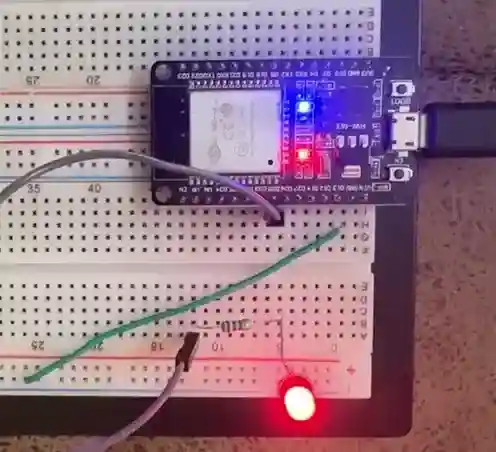
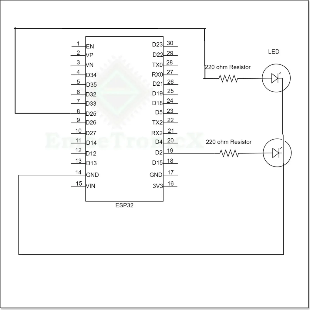
LED interfacing with ESP32 involves connecting an LED to one of the GPIO pins of the ESP32 and controlling its state (on/off) through code. In this demo, we are going to use two GPIOs (GPIO2 which is connected to on board LED and GPIO25).
Connection
- Connect the anode (+) as positive to the LED to a GPIO 2 pin on the ESP32.
- Connect the cathode (-) as negative to the starting point of the resistor.
Source Code – ESP32 GPIO Example (Blinky)
Create the empty project and copy paste the below code to the main.c.
[Please download the complete project from GitHub]
#include <stdio.h>
#include "freertos/FreeRTOS.h"
#include "freertos/task.h"
#include "driver/gpio.h"
#include "esp_log.h"
#include "sdkconfig.h"

static const char *TAG = "ETX_BLINKY";

#define BLINK_GPIO_1 2
#define BLINK_GPIO_2 25

void app_main(void)
{
    /* Reset the pin */
    gpio_reset_pin(BLINK_GPIO_1);
    gpio_reset_pin(BLINK_GPIO_2);

    /* Set the GPIOs to Output mode */
    gpio_set_direction(BLINK_GPIO_1, GPIO_MODE_OUTPUT);
    gpio_set_direction(BLINK_GPIO_2, GPIO_MODE_OUTPUT);

    while (1)
    {
        gpio_set_level(BLINK_GPIO_1, 1);
        gpio_set_level(BLINK_GPIO_2, 1);
        vTaskDelay(1000 / portTICK_PERIOD_MS);
        ESP_LOGI(TAG, "Turning the LED %s!","ON");

        gpio_set_level(BLINK_GPIO_1, 0);
        gpio_set_level(BLINK_GPIO_2, 0);
        vTaskDelay(1000 / portTICK_PERIOD_MS);
        ESP_LOGI(TAG, "Turning the LED %s!","OFF");
    }
}
Overall, this code initializes a GPIO pin on the ESP32, configures it as an output, and then enters an infinite loop, continuously turning an LED connected to GPIO pin ON and OFF with a 1000-mili second delay. Log messages are printed to indicate the state of the LED.
|
|
|
Demo – ESP32 GPIO Example (Blinky)
The below image shows the output the above code.
Push Button Interfacing – Without Interrupt
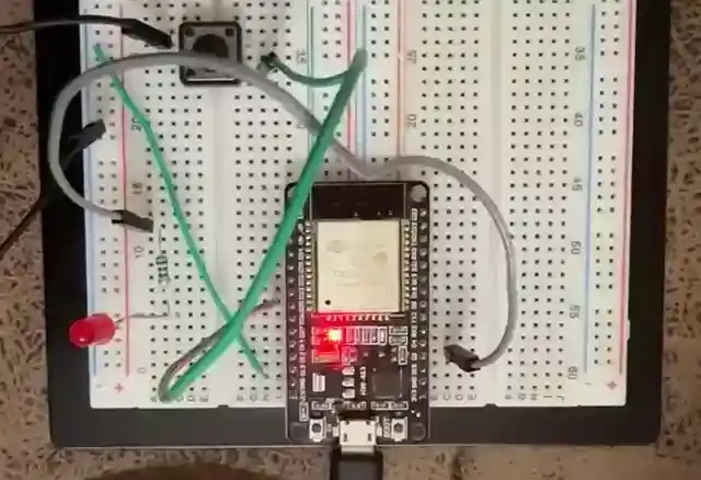
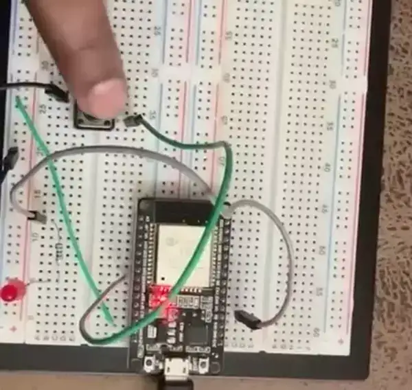
In this example we are going to set one GPIO (GPIO25) as a input and another GPIO (GPIO2) as a output. When we press the button, the LED will be ON and when we release the button, the LED will be OFF.
Connection
- Connect the one end of the push button to GPIO25 and another end of the push button to GND.
- Connect the LED to GPIO2.
Source Code – ESP32 GPIO Input
Create the empty project and copy paste the below code to the main.c.
[Please download the complete project from GitHub]
#include <stdio.h>
#include "freertos/FreeRTOS.h"
#include "freertos/task.h"
#include "driver/gpio.h"
#include "esp_log.h"
#include "sdkconfig.h"

static const char *TAG = "ETX_PUSH_BUTTON";

#define BLINK_GPIO_1 2
#define BLINK_GPIO_2 25

void app_main(void)
{
    /* Reset the pin */
    gpio_reset_pin(BLINK_GPIO_1);
    gpio_reset_pin(BLINK_GPIO_2);

    /* Set the GPIOs to Output mode */
    gpio_set_direction(BLINK_GPIO_1, GPIO_MODE_OUTPUT);
    gpio_set_direction(BLINK_GPIO_2, GPIO_MODE_INPUT);

    /* Enable Pullup for Input Pin */
    gpio_pullup_en(BLINK_GPIO_2);

    while (1)
    {
        if( gpio_get_level(BLINK_GPIO_2) == 0 )
        {
            /* Button is pressed. Turn on the LED */
            gpio_set_level(BLINK_GPIO_1, 1);
            ESP_LOGI(TAG, "Turning the LED %s!","ON");
        }
        else
        {
            /* Button is released. Turn off the LED */
            gpio_set_level(BLINK_GPIO_1, 0);
        }
    }
}
Demo – ESP32 GPIO Input
The below image shows the output the above code.
|
|
|
Push Button Interfacing – Using Interrupt
Connection
- Connect the one end of the push button to GPIO25 and another end of the push button to GND.
- Connect the LED to GPIO2.
Source Code – ESP32 GPIO Interrupt Example
Create the empty project and copy paste the below code to the main.c. The below code toggles the LED with the each button press.
[Please download the complete project from GitHub]
#include <stdio.h>
#include "freertos/FreeRTOS.h"
#include "freertos/task.h"
#include "driver/gpio.h"
#include "esp_log.h"
#include "sdkconfig.h"
#include <inttypes.h>

#define BLINK_GPIO_1 2
#define BLINK_GPIO_2 25

bool gpio_value = false;

static void IRAM_ATTR gpio_isr_handler(void* arg)
{
    /*
        TODO - Implement the debouncing algorithm
        to eliminate the Spurious interrupt trigger.
    */

    /* Disable the Interrupt */
    gpio_intr_disable(BLINK_GPIO_2);
    gpio_isr_handler_remove(BLINK_GPIO_2);

    /* Button is pressed. Toggle the LED */
    gpio_set_level(BLINK_GPIO_1, gpio_value);
    gpio_value = !gpio_value;

    /* Re-Enable the Interrupt */
    gpio_isr_handler_add(BLINK_GPIO_2, gpio_isr_handler, NULL);
    gpio_intr_enable(BLINK_GPIO_2);
}

void app_main(void)
{
    /* Reset the pin */
    gpio_reset_pin(BLINK_GPIO_1);
    gpio_reset_pin(BLINK_GPIO_2);

    /* Set the GPIOs to Output mode */
    gpio_set_direction(BLINK_GPIO_1, GPIO_MODE_OUTPUT);
    gpio_set_direction(BLINK_GPIO_2, GPIO_MODE_INPUT);

    /* Enable Pullup for Input Pin */
    gpio_pullup_en(BLINK_GPIO_2);

    /* Disable pulldown for Input Pin */
    gpio_pulldown_dis(BLINK_GPIO_2);

    /* Configure Raising Edge detection Interrupt for Input Pin */
    gpio_set_intr_type(BLINK_GPIO_2, GPIO_INTR_POSEDGE);

    /* install gpio isr service to default values */
    gpio_install_isr_service(0);

    /* Attach the ISR to the GPIO interrupt */
    gpio_isr_handler_add(BLINK_GPIO_2, gpio_isr_handler, NULL);

    /* Enable the Interrupt */
    gpio_intr_enable(BLINK_GPIO_2);

    while (1)
    {
        /* infinite loop */
    }
}
Demo – ESP32 GPIO Interrupt Example
The below image shows the output the above code.
In our next article, we will see ESP32 UART Communication tutorial.
You can also read the below tutorials.
|
|
|

Embedded Software | Firmware | Linux Devic Deriver | RTOS
Hi, I am a tech blogger and an Embedded Engineer. I am always eager to learn and explore tech-related concepts. And also, I wanted to share my knowledge with everyone in a more straightforward way with easy practical examples. I strongly believe that learning by doing is more powerful than just learning by reading. I love to do experiments. If you want to help or support me on my journey, consider sharing my articles, or Buy me a Coffee! Thank you for reading my blog! Happy learning!

