
This is the Series of tutorials on the STM32 Microcontroller. The aim of this series is to provide easy and practical examples that anyone can understand. In this tutorial, we are going to see Programming a Blue/Black Pill STM32 Board with an ST-Link V2.
The low-cost Chinese STM32 boards like STM32F103 Blue Pill Boards, and STM32F411 Black Pill Boards don’t have the onboard debugger or flasher. So, we have been using the ST-Link V2 Programmer For STM8 and STM32 Dongle which is very low cost. But sometimes it used to create an issue and it doesn’t work. So, we thought of using the ST-LINK V2 in-circuit debugger/programmer for STM8 and STM32. But we don’t find the proper document to check the connection though it is simple. In this article, we will see how to use that step by step.
You can also read our other STM32 Tutorials.
Table of Contents
Official ST-LINK/V2
The ST-LINK/V2 is an in-circuit debugger and programmer for the STM8 and STM32 microcontrollers. The single-wire interface module (SWIM) and JTAG/serial wire debugging (SWD) interfaces are used to communicate with any STM8 or STM32 microcontroller located on an application board.

STM32 applications use the USB full-speed interface to communicate with the STM32CubeIDE software tool or with integrated development environments from third-parties.
Features
- 5 V power supplied by a USB connector
- USB 2.0 full-speed compatible interface
- USB Type-A to Mini-B cable provided
- SWIM specific features:
- 1.65 V to 5.5 V application voltage support on the SWIM interface
- SWIM low-speed and high-speed modes support
- SWIM programming speed rates: 9.7 kbyte/s in low-speed, 12.8 kbyte/s in high-speed
- SWIM cable for connection to an application with an ERNI standard connector
- SWIM cable for connection to an application with pin headers or 2.54 mm pitch connector
- JTAG/serial wire debug (SWD) specific features:
- 1.65 V to 3.6 V application voltage support on the JTAG/SWD interface and 5 V tolerant inputs
- JTAG cable for connection to a standard JTAG 20-pin 2.54 mm pitch connector
- JTAG support
- SWD and serial wire viewer (SWV) communication support
- Direct firmware update support (DFU)
- Status LED blinking during the communication with the PC
- Operating temperature from 0 °C to 50 °C
You can download the drivers from the official page.
Programming a Blue/Black Pill STM32 Board with a ST-LINK V2
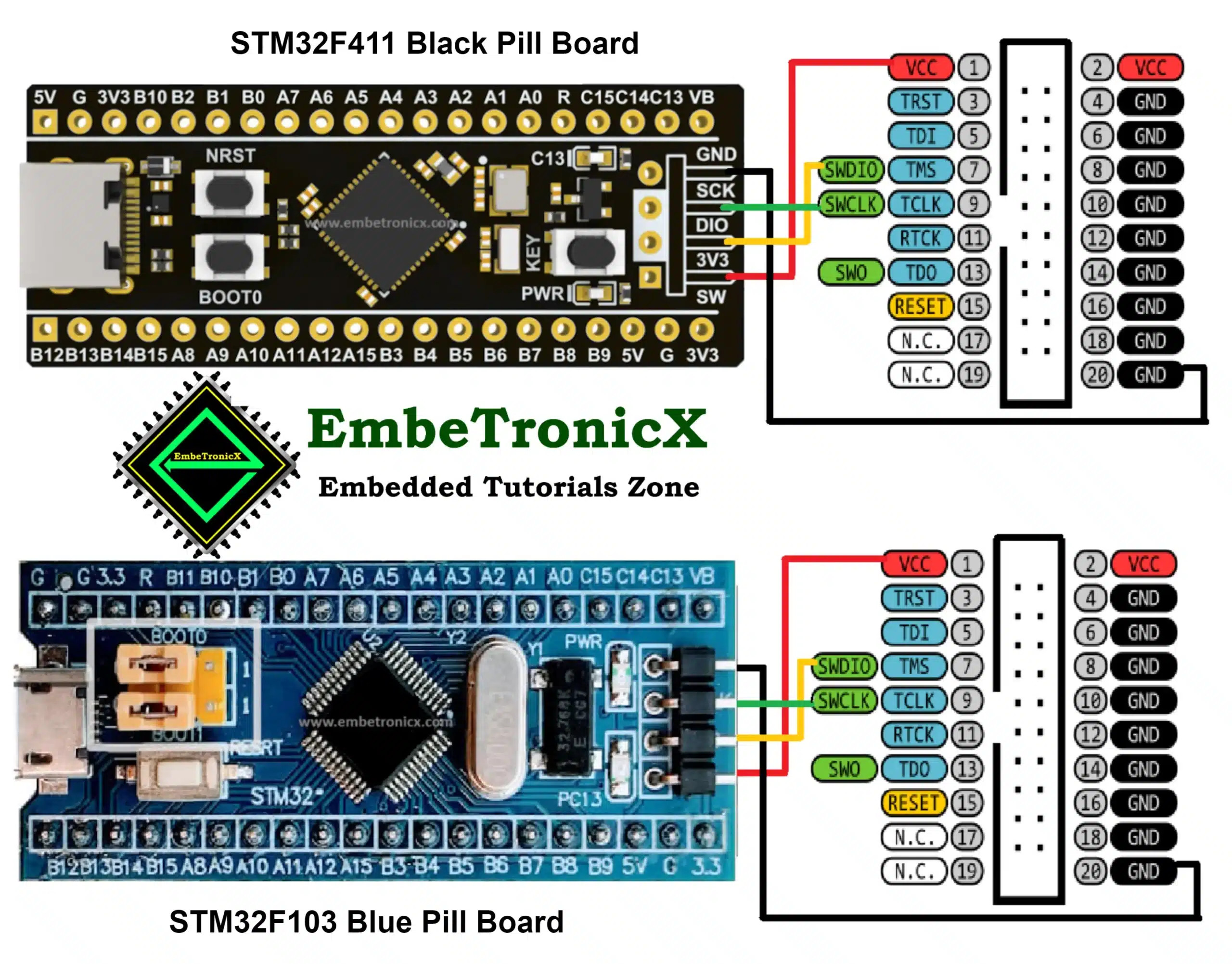
The ST-LINK V2’s pinout is given below.

- ST-Link GND (even-numbered pins from 4 to 20) to Black/Blue Pill Board Ground
- ST-Link SWDIO (pin 7) to Black/Blue Pill Board DIO
- ST-Link SWCLK (pin 9) to Black/Blue Pill Board CLK
- ST-Link VAPP (pins 1 or 2) to Black/Blue Pill Board 3V3
The below illustration explains the connection of both Blue and Black Pill Board.
We hope this would have helped you.
You can read the below tutorials.

Embedded Software | Firmware | Linux Devic Driver | RTOS
Hi, I am a tech blogger and an Embedded Engineer. I am always eager to learn and explore tech-related concepts. And also, I wanted to share my knowledge with everyone in a more straightforward way with easy practical examples. I strongly believe that learning by doing is more powerful than just learning by reading. I love to do experiments. If you want to help or support me on my journey, consider sharing my articles, or Buy me a Coffee! Thank you for reading my blog! Happy learning!
Share this:

Discover more from EmbeTronicX
Subscribe to get the latest posts sent to your email.