
This is the Series of tutorials on the STM32 Microcontroller. This series aims to provide easy and practical examples that anyone can understand. In this tutorial, we will see all the types of Timers available in STM32 and we will see about General Purpose Timers in detail. Then, we will write a program for the timer.
Table of Contents
Prerequisites
Before starting this STM32 GPIO Tutorial, Please go through the below tutorials.
Hardware/Software Requirements
In this tutorial, we are going to see the timer for the STM32F407 Discovery Board
We have our own EmbeTronicX Store called ChipTronicX. You can purchase the hardware from ChipTronicX at great prices.
- STM32F407 Discovery Board (ARM Cortex M4)
- LEDs
- STM32CubeIDE
STM32F407 Timer Tutorial
What is a Timer?
According to Wiki, A timer is a specialized type of clock used for measuring specific time intervals. A timer that counts from zero upwards for measuring the time elapsed is often called a stopwatch. It is a device that counts down from a specified time interval and is used to generate a time delay. Like that, STM32 also has a few timers in it. And not only counting the time but, it is also used for many purposes. We will see those
STM32 Timer Introduction
The timer (sometimes referred to as a counter) is an essential peripheral in microcontrollers. There are different types of timers available in the STM32 microcontrollers. Each can operate in multiple modes and perform so many tasks. Before we get into that, we will have to know about the clock in the STM32. Yes. Timer and Clock are two different things and not the same.
System Clock
The system clock is the heart of the microcontroller. Without the clock, the controller can’t run. We can provide the clock in three different ways to the STM32. Those are,
- HSI Oscillator Clock (High-Speed Internal Clock)
- HSE Oscillator Clock (High-Speed External Clock)
- Main PLL Clock (Phase Locked Loop)
And also it has two secondary clock sources.
- Low-speed internal RC (LSI RC). This drives the independent watchdog and, optionally, the RTC used for Auto-wakeup from the Stop/Standby mode.
- Low-speed external crystal (LSE crystal) which optionally drives the RTC clock (RTCCLK)
The first three clocks are used to drive the system clock for the microcontroller. The final two are low-speed clocks and are primarily used to drive the watchdogs.
The HSI or HSE will be selected based on our configuration and the output will be given to the PLL. Using this PLL, we can control (increase or decrease) the System Clock value. When the System Clock signal switches from high to low, one instruction will be executed by the processor. That’s why the speeder clock executes the instruction fast.
Once the System clock is generated, this clock will be distributed to the peripherals and others using AHB Bus (Advanced High-Performance Bus), APB1 Bus (Low-speed Advanced Peripheral Bus), and APB2 Bus (High-speed Advanced Peripheral Bus). Each of these clocks can be scaled using prescalers.
Yes, I understand. This might confuse a few people. The point that I want to convey is, that the timer always needs a clock source and the derived clock of this APB is given to the timer. We can control the clock values using the prescaler. In the below example, we are going to use the internal clock (HSI) for demonstration.
STM32 Timer
Now, we have derived the clock from the APB1 or APB2 bus. That output can be controlled using the prescaler. Assume that we have an 8-bit timer and its initial value is 0 (we can change the initial value). When the input clock of the timer goes from high to low, it counts the value from 0 to 1. Likewise, it goes to 255 as this is an 8-bit timer. If this is a 16-bit timer, then it goes till 65535. Most timers will “roll over” once they reach their max value. So, our 8-bit timer would start over again from 0 once it reaches 255. This is the working method of the timer. We can control this timer to do many tasks like counter, capture, etc using the timer registers.
STM32 Timer Modes
We can configure the timer and it can be used in the below modes.
- Timer Mode (Time base generator)
- Counter Mode
- Input Capture Mode
- PWM Input Mode
- Forced output mode
- Output Compare Mode
- PWM Mode
- One-Pulse Mode
- and more
Timer Mode (Time base generator)
The timer can be used as a time base generator. Depending on the clock, prescaler, auto-reload, and repetition counter (if present) parameters, the 16-bit timer can generate an update event from a nanosecond to a few minutes. For the 32-bit timer, the range is larger. This is used to generate the delay, specific operation done in each specific time interval (periodic operations) and etc.
Counter Mode
In this mode, we can count the external events. The timer value will be incremented based on external events. In this mode, the timer will get the clock from the external source through the external timer input pin. This mode is really helpful in many situations when you need to implement a digital counter without polling input pins or periodically reading a GPIO.
Input Capture Mode
The timer can be used in input capture mode to measure an external signal. The Input Capture Mode is another useful feature of Timer, usually used for frequency counting. The input capture module has the task of capturing the current value of the timer counter upon an input event. The input capture function is used in many applications such as:
- Pulse width measurement
- Period or timing measurement (Precisely time the duration between rising and falling edges of digital inputs)
- Capturing the time of an event
Output Compare Mode
In output compare mode, a timer module controls an output waveform or indicates when a period of time has elapsed. When a match is detected between the output compare register (OCR) and the counter, the output compare function assigns the corresponding output pin to a programmable value defined by the output compare mode defined by the programmer.
The output compare pin can be driven high, or low, toggles its state, or stay unchanged based on the user configuration. We can configure the below modes.
- Output compare timing – When the counter value and the capture/compare register are matched, the channel output is not affected and this is used for the timing base.
- Output compare active – When the counter value and the capture/compare register are matched, it forces the channel output to the active level.
- Output compare inactive – When the counter value and the capture/compare register are matched, it forces the channel output to the inactive level.
- Output compare toggle – When the counter value and the capture/compare register are matched, it toggles the channel output.
- Output compare forced active/inactive – OCREF is forced high (active mode) or low (inactive mode) independently from the counter value.
One-Pulse Mode
One pulse mode (OPM) is a particular case of the input capture mode and the output compare mode. It allows the counter to be started in response to a stimulus and to generate a pulse with a programmable length after a programmable delay.
Forced output mode
In this output mode, each output compare signal can be forced to active or inactive level directly by the software, independently of any comparison between the output compare register and the counter.
PWM Mode
I hope everyone must aware of this mode. In this mode, we can produce a square wave with a particular duty cycle, period, frequency, etc. Using this, we can do many actions like changing the brightness of the light, speed of the motor, etc.

PWM Input Mode
This mode is a particular case of input capture mode. The user can measure the period and the duty cycle of the PWM applied on the pin.
Each timer will support a few modes. We will see those modes in each timer.
Types of STM32 Timers
Each STM32 variant controller has several built-in timers. They are numbered from TIM1 to TIM20, and grouped into different types.
- General Purpose Timers (This tutorial)
- Advanced Control Timers
- Basic Timers
- Low Power Timers
Usually, the higher-end chips will have more timers in them. The details of STM32 timers are quite a rabbit hole, but we’ll keep it simple in this tutorial. We will see the above-mentioned timers one by one in our upcoming tutorials.
As a timer is a vast concept, we will see the timer one by one. In this tutorial, we will see the General Purpose Timers.
General Purpose Timers in STM32
The general-purpose timers consist of a 16-bit or 32-bit auto-reload counter driven by a programmable prescaler. These timers will be used for a variety of purposes and can be used in Input capture mode, Output compare mode, and PWM mode by programming different configurations. The timers are completely independent and do not share any resources. They can be synchronized together. We can measure or generate the Pulse lengths and waveform from a few microseconds to several milliseconds s using the timer prescaler and the RCC clock controller prescalers.
General-purpose timer features
- 16-bit or 32-bit (based on the microcontroller) up, down, up/down auto-reload counter.
- 16-bit programmable prescaler used to divide (also “on the fly”) the counter clock frequency by any factor between 1 and 65535.
- Up to 4 independent channels for:
- Input capture
- Output compare
- PWM generation (Edge- and Center-aligned modes)
- One-pulse mode output
- Synchronization circuit to control the timer with external signals and to interconnect several timers.
- Interrupt/DMA generation on the following events:
- Update: counter overflow/underflow, counter initialization (by software or internal/external trigger)
- Trigger event (counter start, stop, initialization or count by internal/external trigger)
- Input capture
- Output compare
- Supports incremental (quadrature) encoder and hall-sensor circuitry for positioning purposes.
- Trigger input for external clock or cycle-by-cycle current management.
STM32F407 Timer
STM32F4 has below timer modules,
- TM1 and TIM8– Advanced-control timers
- TIM2 to TIM5 – General-purpose timers
- TIM8 to TIM14 – General-purpose timers
- TIM6 and TIM7 – Basic timers
In this post, we will see the General-Purpose timers (TIM2 to TIM5) in the STM32F4. The block diagram of the general-purpose timer is given below.
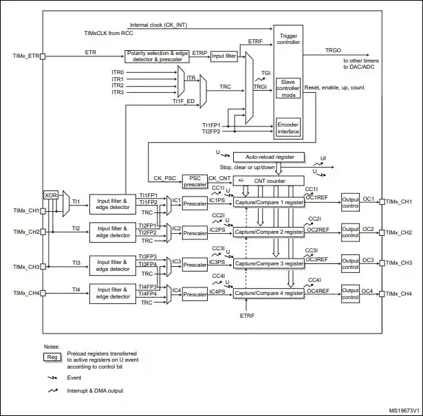
You can refer to the respective User manual for a better understanding.
STM32F407 Timer Example – Generate Simple Delay (Timer mode)
In this example, we are going to set up TIM2 on the STM32F407 to generate an interrupt every one second, which will toggle onboard LED (PD13) each time the timer overflows.
Project Creation
- Open STM32CubeIDE and create a new project
- Select the STM32F407VGT6 microcontroller
- Give Project name as per your convenient
- Go to System Core > RCC then select ‘Crystal/Ceramic Resonator’ from the High Speed Clock feature.
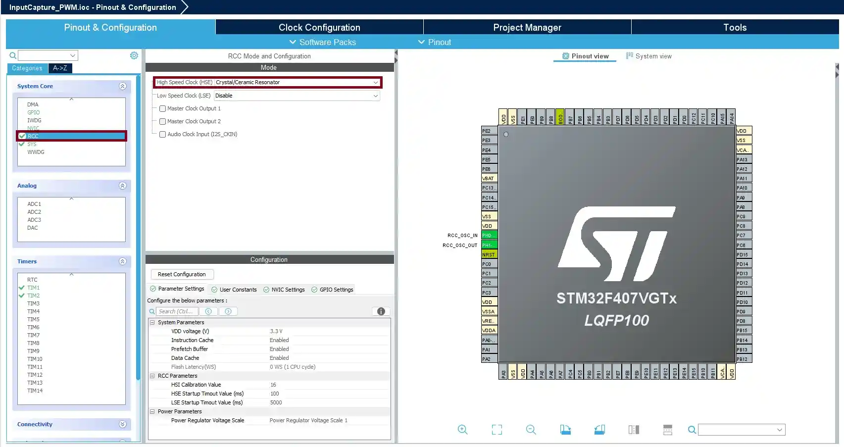
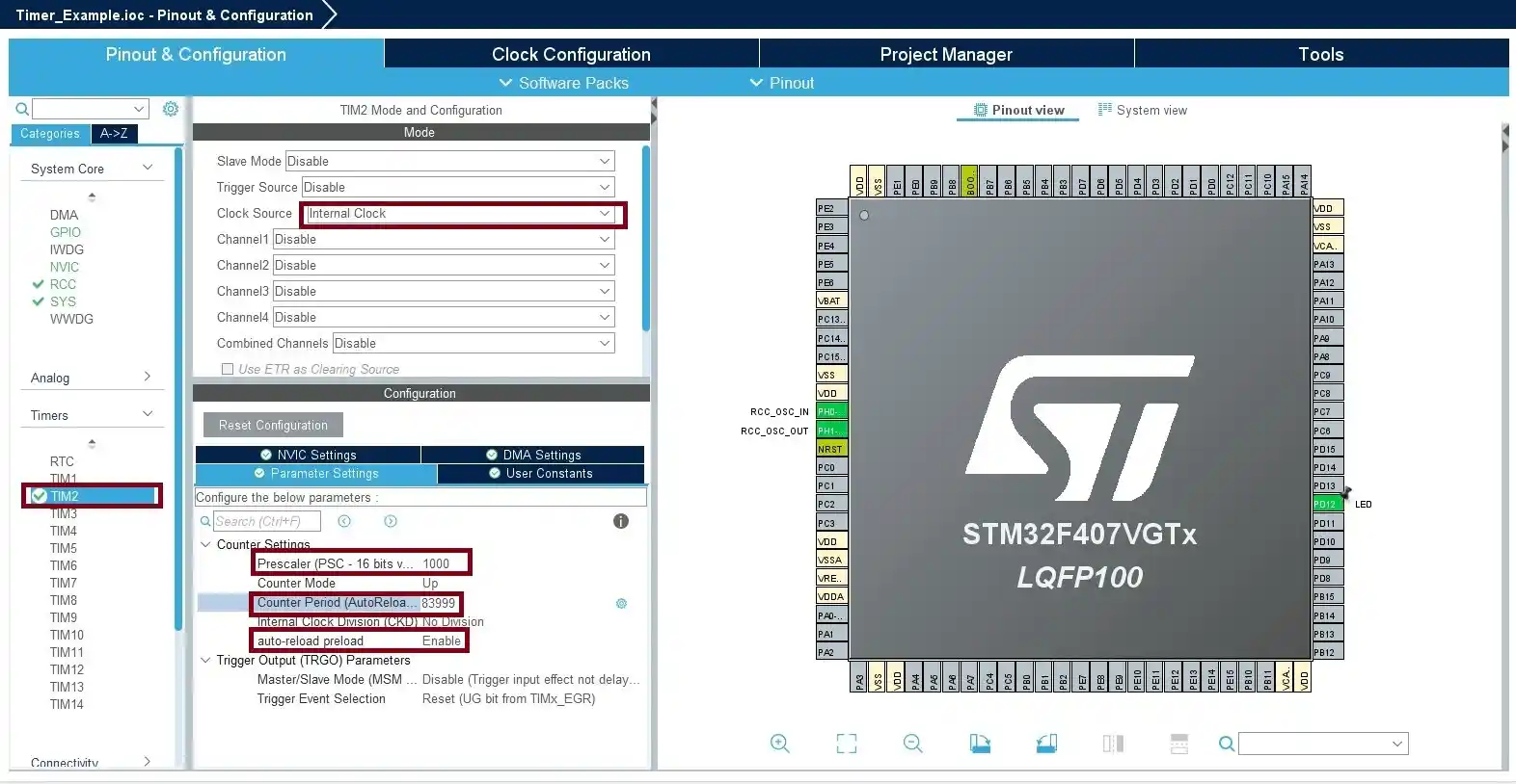
- Configure TIM2: In Pin & Configuration tab under Timers select “TIM2“
- Prescalar Configuration:
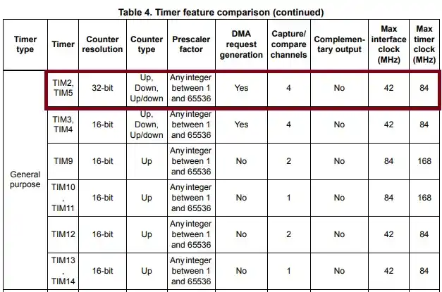
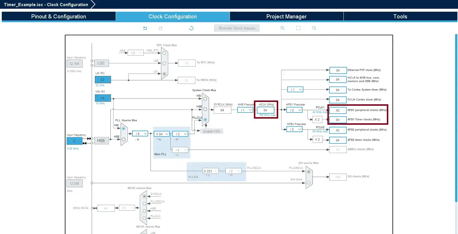
- According to block diagram of STM32F407, “TIM2” is connected to APB1 clock and the Maximum Timer clock is 84MHZ
- To achieve a 1-second delay, the timer should overflow once per second. Consider Fck is 84MHz and prescaler is 1000
- Find Timer Frequency (F_timer)
- F_Timer = Fck / Prescaler ==> 84000000 /1000 ==> 84000
- So F_Timer is 84000
- Find Auto Re-load value(ARR)
- To get a 1-second(T delay) delay, we substitute into the formula: ARR= (Ftimer×Tdelay) −1 ==> (84,000×1)−1==> 83,999
- So, the ARR value resulting in a 1-second delay is 83,999.
- In parameter setting Enter prescaler, ARR value, and enable the auto-reload preload and set “PD13” as “GPIO output, that is use for LED.
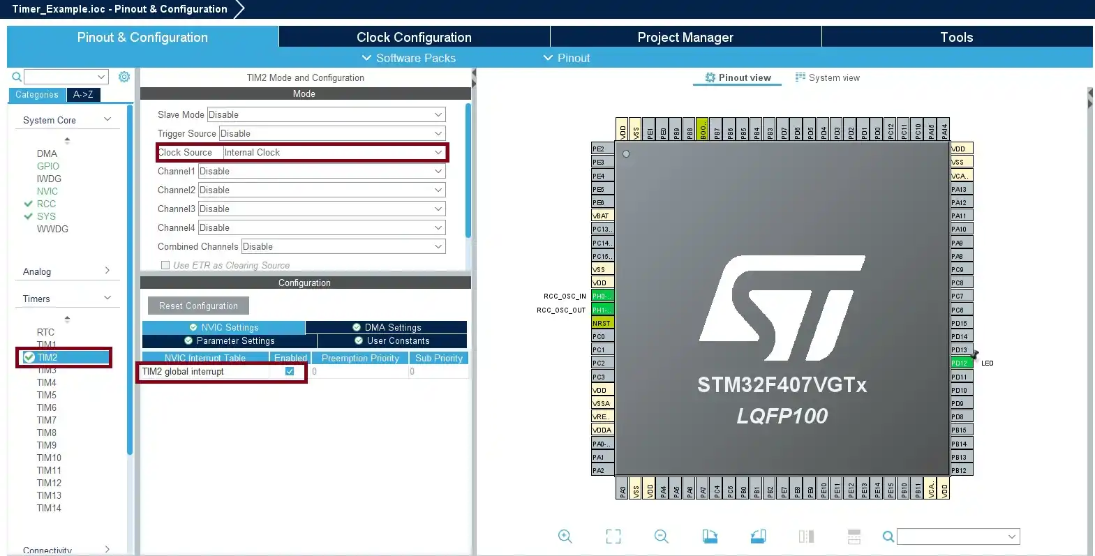
- Enable TIM2 global interrupt NVIC Settings
- APB1 Configuration: Since “TIM2” is connected to APB1 that should be 84MHz. in HCLK(MHz) assign 84 and press enter. To achieve this value we need to change the APB1 Prescaler
- After all configuration is been done to save click Ctrl+ S.
Source Code
Note: Whenever you are adding your code, you must include your code between the USER CODE BEGIN and USER CODE END. If you add your code anywhere else, then it will be removed when you regenerate the code. Keep this in your mind.
- First we need to Enable the “TIM2“,
  /* USER CODE BEGIN 2 */
  HAL_TIM_Base_Start_IT(&htim2);

  /* USER CODE END 2 */
- Then we will add the timer interrupt ISR handler callback function. It is responsible to check the interrupt pin source, then toggle the output GPIO pin accordingly.
/* USER CODE BEGIN 4 */
 void HAL_TIM_PeriodElapsedCallback(TIM_HandleTypeDef* htim)
 {
     HAL_GPIO_TogglePin(GPIOD, GPIO_PIN_12);
 }

/* USER CODE END 4 */
If you want the full source code, Please check our GitHub
Output
[To Be Added]
If you want to read the STM32 Timer Tutorial for bare metal, Please read it here STM32 Timer Tutorial-Bare Metal

Embedded Software Developer who is passionate about Embedded Systems.
Share this:

Discover more from EmbeTronicX
Subscribe to get the latest posts sent to your email.