

This is the Series of tutorials on the STM32 Microcontroller. The aim of this series is to provide easy and practical examples that anyone can understand. In this tutorial, we are going to see the STM32F103 GPIO Tutorial using STM32CubeIDE.
This tutorial aims to help beginners to understand the basics of STM32 GPIO programming using the higher-level abstractions, making it suitable for those who want to learn the fundamentals of microcontroller interaction. If you want to learn GPIO programming without HAL, you can read this Baremetal STM32 GPIO Tutorial.
You can also read, Getting Started with STM32 RTOS, STM32 GPIO RTOS tutorial, and STM32 Bootloader Tutorial.
Table of Contents
Prerequisites
Before starting this STM32F103 GPIO Tutorial, Please go through the below tutorials.
Hardware Requirements
- STM32F103C8T6 Blue Pill board (ARM Cortex M0)
- LED
- Pushbutton
STM32F103 GPIO Tutorial using STM32CubeIDE
Writing On a Port Pin
Writing data to a designated port refers to transmitting data from the controller to any connected peripheral device. Here, an LED visualizes the data leaving the parallel port.
Prototype
HAL_GPIO_WritePin (GPIO_TypeDef* GPIOx, uint16_t GPIO_Pin, GPIO_PinState PinState)
Reading from a Port
The reading operation involves retrieving data from any peripheral device. In this case, we are using a simple push-button (switch) to provide input to the port pins.
Prototype
HAL_GPIO_WritePin (GPIO_TypeDef *GPIOx, uint16_t GPIO_Pin, GPIO_PinState PinState)
STM32F103CBT6 Blue Pill board
The STM32F103C8T6 microcontroller, which is used in the Blue Pill development board, has 5 GPIO ports: Port A (GPIOA), Port B (GPIOB), Port C (GPIOC), Port D (GPIOD), and Port E (GPIOE). These ports are mapped to different pins on the microcontroller, with each port providing various functionalities such as general-purpose I/O, analog inputs, communication peripherals (UART, SPI, I2C), and other specialized functions.
LED Interfacing
This board comes with user LED connected with PC13 pin of PORTC through a current limiting resistor.
Here we are using onboard LED from Port C and pin 13, Further we will see how to create a project using STM32cube IDE and to configure pin PC13 as an LED in STM32CubeIDE, follow these steps:
Project Creation
- Open STM32CubeIDE and create a new STM32 project for your target microcontroller.
- Once the project is created, open the
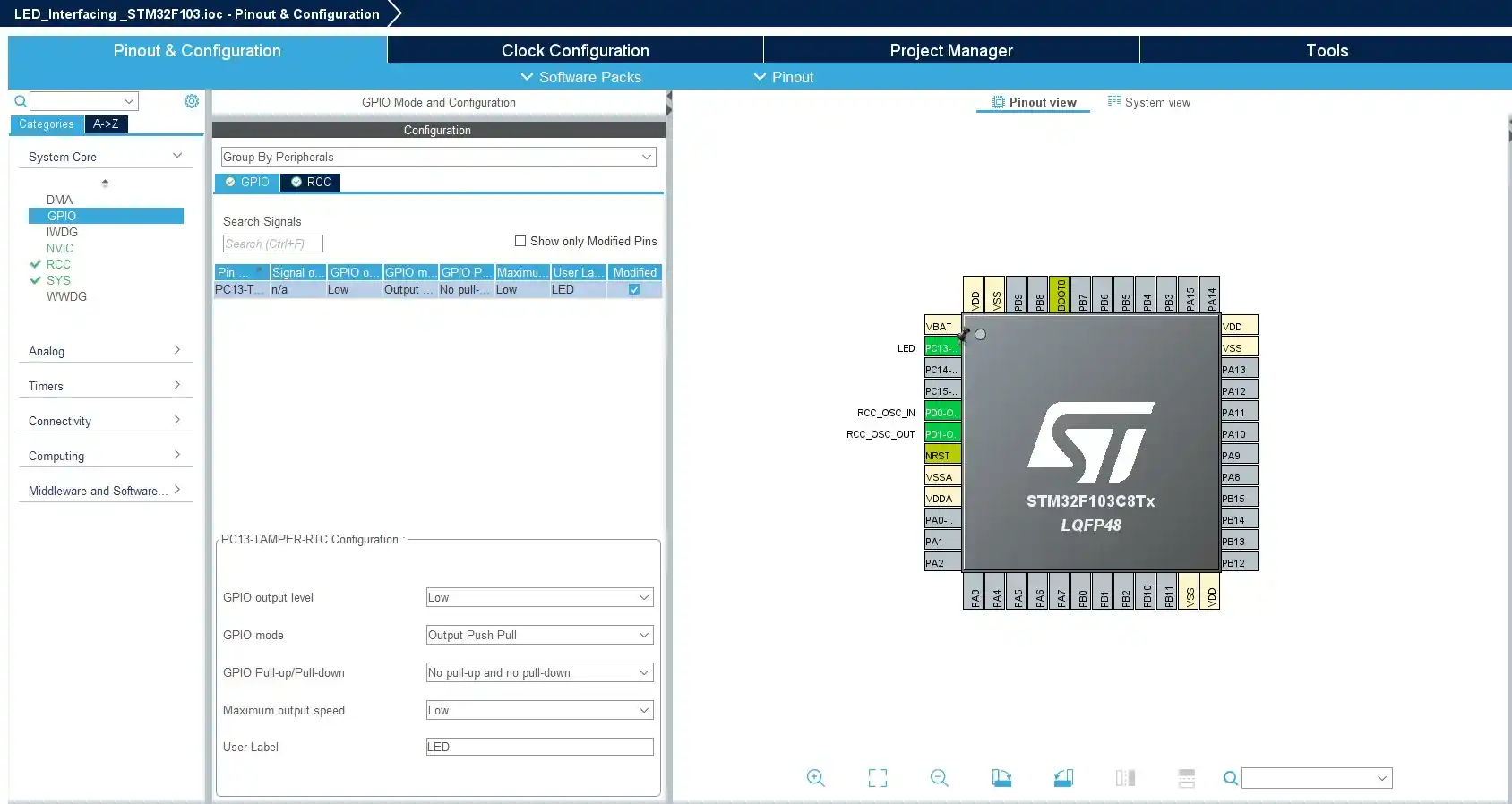
.iocfile to access the configuration settings. - In the Pinout & Configuration tab, find the pin labelled PC13
- Click on PC13 to configure it. In the dropdown menu, select “GPIO_Output“. This sets the pin as a digital output.
- You can configure the output level (default is usually low), speed, pull-up/pull-down resistors, etc., as per your requirements.
- In this tutorial I configured as no pull-up and no pull-down. Once all the configurations are done save with CTRL+S
STM32F103 GPIO Tutorial – Source Code
- Open the
main.cfile in theCore/Srcdirectory. In themain()function, you can toggle the LED with something like:
  /* Infinite loop */
  /* USER CODE BEGIN WHILE */
  while (1)
  {
     HAL_GPIO_WritePin(GPIOC, GPIO_PIN_13, GPIO_PIN_SET);   // Turn LED on
     HAL_Delay(1000);
     HAL_GPIO_WritePin(GPIOC, GPIO_PIN_13, GPIO_PIN_RESET); // Turn LED off
     HAL_Delay(1000);
    /* USER CODE END WHILE */

    /* USER CODE BEGIN 3 */
  }
  /* USER CODE END 3 */
You can download the complete project from GitHub
Output
[To Be Added]
Push-button Interfacing
To use a push button with STM32F1, we will configure GPIO pins of STM32F103C8T6 microcontroller as a digital input pin. In this Push button Interfacing, we will control onboard LEDs of STM32F1 with an onboard push button.
The user Push button connected to pin zero of PORTA(PA0). We will use this push button as a digital input to manage the onboard LEDs on the board.
When interfacing a push button with a microcontroller, our goal is to detect whether the button is pressed or not. Depending on the circuit configuration, pressing or releasing the button produces either a logic high or logic low output.
Controlling LEDs with Push Button STM32F103 Blue Pill Board
To demonstrate, we will use a push button to control the onboard LED of the STM32 board.
- The pin A0 will read the input from the push button. If the state is active high, it will turn on the onboard LED of the STM32F103 Blue pill board. Since the LED is connected to the PC13 pin in a No pull-up and No pull-down configuration, it will typically show an active high output.
- When the push button is pressed, the LED will turn on; otherwise, it will stay off.
- Now, we will see how to configure the pushbutton as input. We already know the LED configuration from the previous example.
Further, we will see how to create a project using STM32cube IDE. To configure pin PA0 as an push button in STM32CubeIDE, follow these steps:
Project Creation
- Open STM32CubeIDE and create a new STM32 project for your target microcontroller.
- Once the project is created, open the .ioc file to access the configuration settings.
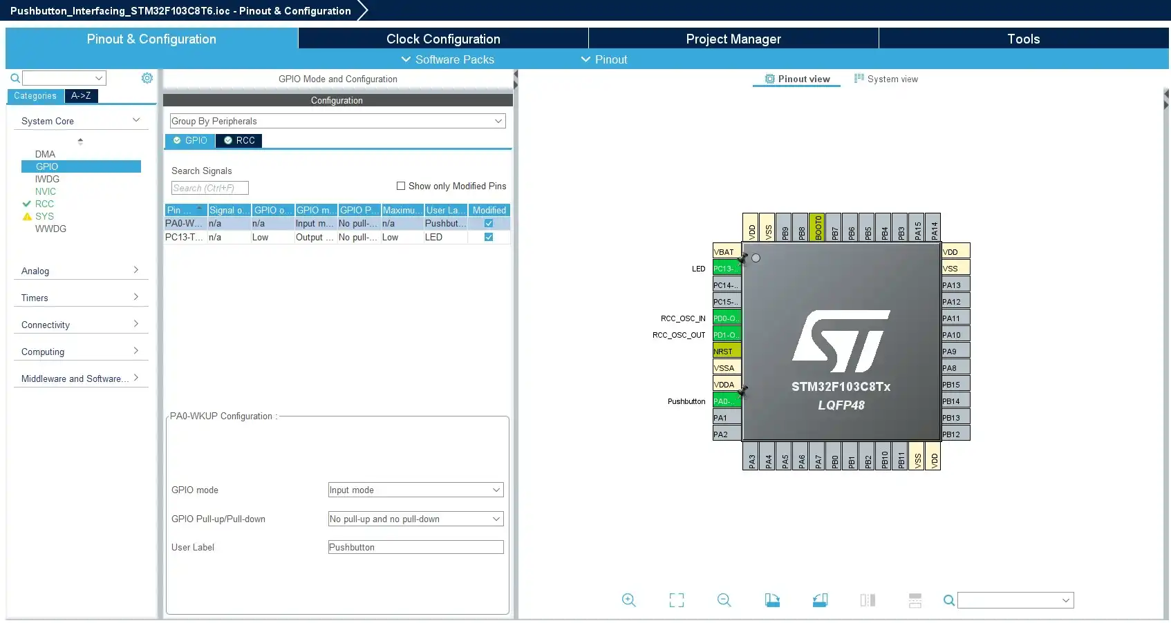
- In the Pinout & Configuration tab, find the pin labelled PA0
- Click on PA0 to configure it. In the dropdown menu, select “GPIO_Input“. This sets the pin as a digital output. This sets the pin as a digital input and PA0 pin is configured with Pull-Up configuration.
- Click on PC13 to configure it. In the dropdown menu, select “GPIO_Output“.
Connection
- One terminal of the push button is connected to PA0 (the GPIO pin on the STM32F103C8T6).
- GND: The other terminal of the push button is connected to GND.
STM32F103 GPIO Tutorial – Source Code
- Open the
main.cfile in theCore/Srcdirectory. In themain()function, you can toggle the LED with something like:
  /* Infinite loop */
  /* USER CODE BEGIN WHILE */
  while (1)
  {
    if (HAL_GPIO_ReadPin(GPIOA, GPIO_PIN_0) == 1)      // if Button pressed
    {
       HAL_GPIO_WritePin(GPIOC, GPIO_PIN_13, GPIO_PIN_SET);   // Turn on the LED
    }
    else
    {
      HAL_GPIO_WritePin(GPIOC, GPIO_PIN_13, GPIO_PIN_RESET); // Turn off the LED
    }
    /* USER CODE END WHILE */

    /* USER CODE BEGIN 3 */
  }
  /* USER CODE END 3 */
You can download the complete project from GitHub
Output
[To Be Added]
If you want to learn about other STM32 Microcontrollers GPIO Tutorials, You can read the below tutorials:
- STM32F407 Discovery Board Tutorial
- STM32F411CE Black Pill board Tutorial
- STM32F767Zi Nucleo board Tutorial
You can also read the below tutorials.

Embedded Software Developer who is passionate about Embedded Systems.
Share this:

Discover more from EmbeTronicX
Subscribe to get the latest posts sent to your email.