
This is the Series of tutorials on the STM32 Microcontroller. This series aims to provide easy and practical examples that anyone can understand. This tutorial demonstrates how to use the Timer in the STM32F407 with STM32CubeIDE. In our last tutorial, we have the Introduction of Timers and General Purpose Timers. If you want to read about it click here General Purpose timer
Table of Contents
Prerequisites
Before starting this STM32 GPIO Tutorial, Please go through the below tutorials.
Hardware/Software Requirements
In this tutorial, we are going to see the timer for the STM32F407 Discovery Board
We have our own EmbeTronicX Store called ChipTronicX. You can purchase the hardware from ChipTronicX at great prices.
- STM32F407 Discovery Board (ARM Cortex M4)
- LEDs
- STM32CubeIDE
Advanced Control Timer in STM32F407
The Advanced Control Timer in the STM32F407 microcontroller (TIM1 and TIM8) is used for various applications that require precise timing and control. These timers are particularly beneficial in motor control systems, including BLDC motors, servo motors, and stepper motors, where they generate high-resolution PWM signals to regulate motor speed and direction. Advanced-control timers can also produce complementary PWM outputs, with dead-time insertion to ensure safe switching in circuits like H-bridges, preventing short circuits and ensuring smooth motor control.
In addition to motor control, these timers are used in frequency measurement applications, capturing external events via input capture channels, and for synchronizing multiple outputs to ensure precise coordination across devices. The timers also support encoder interfaces, which are essential for tracking rotational position in robotic systems, CNC machines, or any application requiring precise motion control.
Advanced control timers are also commonly used in applications requiring PWM signal generation for tasks like LED brightness control, power regulation, or audio signal generation, where precise control over frequency and duty cycle is necessary. Furthermore, the integration of DMA (Direct Memory Access) support allows for efficient data transfer without burdening the CPU, making the system more responsive and efficient.
features
- 16-bit up, down, up/down auto-reload counter.
- 16-bit programmable prescaler allowing dividing (also “on the fly”) the counter clock
frequency either by any factor between 1 and 65536. - Up to 4 independent channels for:
– Input capture
– Output compare
– PWM generation (Edge and Center-aligned mode)
– One-pulse mode output - Complementary outputs with programmable dead-time
- Synchronization circuit to control the timer with external signals and to interconnect
several timers together. - Repetition counter to update the timer registers only after a given number of cycles of
the counter. - Break input to put the timer’s output signals in reset state or in a known state.
- Interrupt/DMA generation on the following events:
– Update: counter overflow/underflow, counter initialization (by software or
internal/external trigger)
– Trigger event (counter start, stop, initialization or count by internal/external trigger)
– Input capture
– Output compare
– Break input - Supports incremental (quadrature) encoder and hall-sensor circuitry for positioning
purposes - Trigger input for external clock or cycle-by-cycle current management
Block Diagram
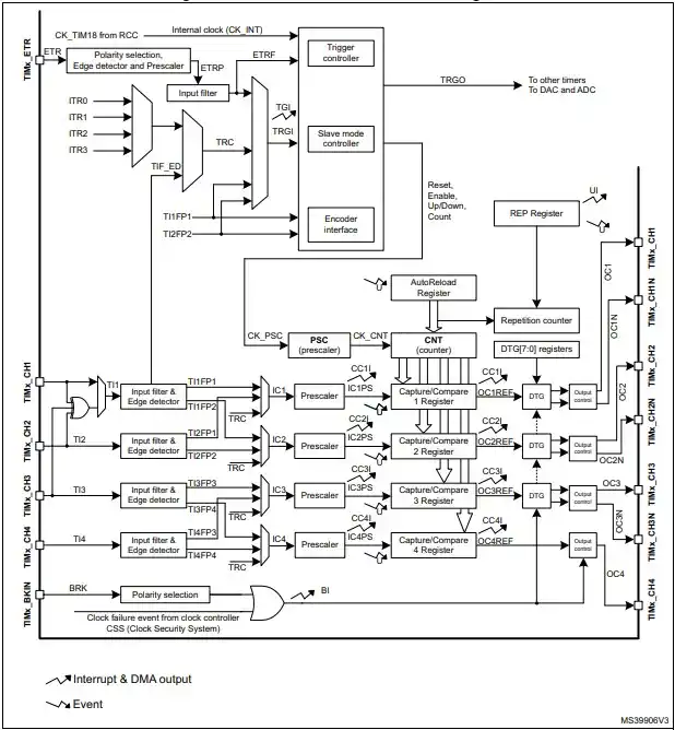
You can refer to the respective User manual for a better understanding.
STM32F407 Advanced Control Timer Example
What is PWM?
PWM (Pulse Width Modulation) is a method used to control the amount of power delivered to a device by adjusting how long a signal stays “on” and “off.” It works by switching the signal between high (on) and low (off) states at a fixed speed, and the duty cycle determines how much time the signal spends in the “on” state.
Applications of PWM
- Motor Speed Control: By adjusting the duty cycle, you control how much power the motor gets, affecting its speed.
- LED Brightness Control: For LEDs, adjusting the duty cycle changes how long the light is on, controlling brightness. A higher duty cycle makes the LED appear brighter.
- Power Regulation: PWM is used in power supplies to efficiently convert one voltage level to another, such as in DC-DC converters.
- Audio Generation: PWM can be used to generate audio signals by rapidly switching between two voltage levels at a frequency that human ears perceive as sound.
PWM Generation
The TIM1 timer is capable of generating Pulse Width Modulation (PWM) signals with high precision. This is useful in a variety of applications, such as motor control, LED brightness adjustment, and power regulation.
As per the Block diagram of STM32F407, TIM1 is connected with APB2
Project Creation
- Open STM32CubeIDE and create a new project
- Select the STM32F407VGT6 microcontroller
- Give Project name as per your convenient,For this project I’m Giving it as “PWM_Generation“
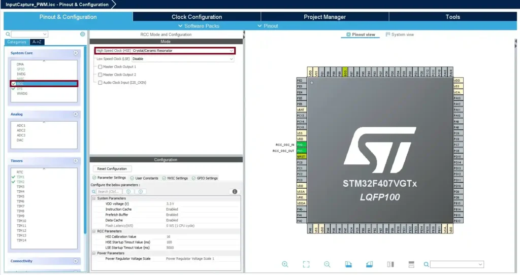
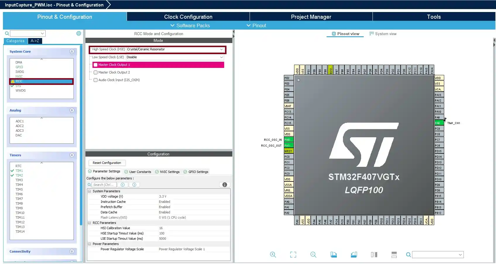
- Go to System Core > RCC then select ‘Crystal/Ceramic Resonator’ from the High Speed Clock feature.
- Configure TIM1:
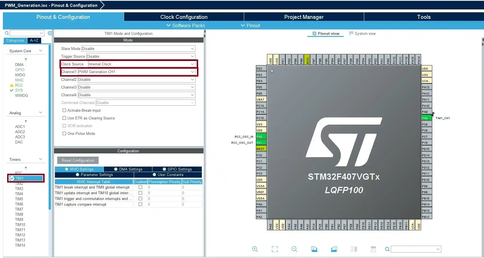
- In Pin & Configuration tab under Timers select “TIM1“ and configure it in PWM Generation CH1 mode and clock source as “Internal Clock“
- STM32CubeMX automatically assigns PA8 as the PWM output pin for TIM1 Channel 1. If not, manually select PA8 as an alternate function.
- Timer Configuration:
- Prescaler Calculation: First, determine the Prescaler value to set the timer’s input clock to an appropriate frequency.The general formula for the timer input frequency is:
Timer Input Frequency= System Clock(SCLK) / (Prescaler+1) - We can choose an appropriate Prescaler value based on the desired PWM frequency. Let’s assume we want to generate a PWM signal with a frequency of 1 kHz (1000 Hz). Here I’m considering Prescaler value is 167.
- The Timer Input Frequency is: 168000000 /(167+1) ==> 10000000 ==> 1 MHz
- Prescaler Calculation: First, determine the Prescaler value to set the timer’s input clock to an appropriate frequency.The general formula for the timer input frequency is:
- Calculate the ARR (Auto-Reload Register):
- The ARR specifies each PWM cycle’s duration (the PWM signal’s frequency).
- Now we can calculate the ARR,
ARR = (Timer Input Frequency / PWM Frequency)-1==> (1000000 /1000) -1 ==> 999. So ARR is 999
- Calculate the CCR for 50% Duty Cycle:
- The CCR controls how long the PWM signal stays high (the duty cycle). The formula calculates the position of the high state in the PWM cycle.
CCR = (ARR x Duty Cycle) / 100==> (999 X 50)/100 ==>499.50. so CCR is 500.
- Go to System Core > RCC then select ‘Crystal/Ceramic Resonator’ from the High Speed Clock feature.
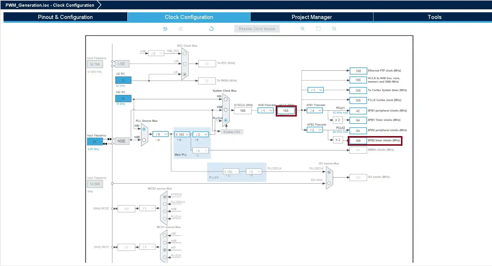
- Clock Configuration:
- In the Clock Configuration tab, adjust HCLK and ABP2 as 168MHz
- After all configuration is been done to save click Ctrl+ S.
Source Code
Note: Whenever you are adding your code, you must include your code between the USER CODE BEGIN and USER CODE END. If you add your code anywhere else, then it will be removed when you regenerate the code. Keep this in your mind.
- First, we need to Enable the “TIM1“, to start the PWM on TIM1 Channel 1
  /* USER CODE BEGIN 2 */
  HAL_TIM_PWM_Start(&htim1, TIM_CHANNEL_1);
  /* USER CODE END 2 */
- This loop gradually Increases the duty cycle of the PWM signal from 0% to 100%. and progressively decreases the PWM duty cycle from 100% back to 0%, stepping down by 1 with a 100 ms delay between each change.
 /* Infinite loop */
  /* USER CODE BEGIN WHILE */
  while (1)
  {
    for (int step= 0; step<= htim1.Init.Period; step++)
    {
          __HAL_TIM_SET_COMPARE(&htim1, TIM_CHANNEL_1, step);
          HAL_Delay(10);
    }
    for (int step= htim1.Init.Period; step>= 0; step--)
    {
        __HAL_TIM_SET_COMPARE(&htim1, TIM_CHANNEL_1, step);
        HAL_Delay(100);
    }
    /* USER CODE END WHILE */

    /* USER CODE BEGIN 3 */
  }
  /* USER CODE END 3 */
}
If you want the full source code, Please check our GitHub
Output
[To Be Added]
If you want to read the STM32 Timer Tutorial for bare metal, Please read it here STM32 Timer Tutorial-Bare Metal

Embedded Software Developer who is passionate about Embedded Systems.
Share this:

Discover more from EmbeTronicX
Subscribe to get the latest posts sent to your email.